7.2 Computer systems, sub-systems and decomposition
Large computer systems become easier to understand and develop when they are broken into smaller sub-systems. Topic 7.2 explains top-down design, stepwise refinement, input-process-output-storage decomposition, structure diagrams, flowcharts and Cambridge-style pseudocode.
The computer system and its sub-systems
A computer system is made up of software, data, hardware, communications and people. A system can be divided into sub-systems, and each sub-system can be divided again until each part performs a single action.
Top-down design means starting with the whole system and decomposing it into smaller sub-systems. Repeatedly breaking those sub-systems down into smaller parts is called stepwise refinement.
This modular approach makes complex systems easier to understand, develop and test. On large projects, different programmers can work on separate sub-systems at the same time, reducing development and testing time. Each sub-system can be implemented as a subroutine, with its logic represented using flowcharts or pseudocode.
Decomposing a problem
Any computer-system problem can be decomposed into four component types:
| Component | Meaning |
|---|---|
| Inputs | Data entered while the system is active. |
| Processes | Tasks performed using input data and any previously stored data. |
| Outputs | Information displayed or printed for users. |
| Storage | Data saved on an appropriate medium for future use. |
Textbook example: alarm app
- Inputs: set an alarm time, remove an alarm time, switch an alarm off, press snooze.
- Processes: compare current time with alarm time, store/remove alarm times, manage snooze.
- Outputs: sound or tune when the alarm or snooze time is reached.
- Storage: the alarm time or times that have been set.
Methods used to design and construct a solution to a problem
The textbook identifies three formal methods that Cambridge IGCSE Computer Science students need to use: structure diagrams, flowcharts and pseudocode.
Structure diagrams
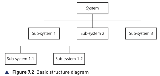
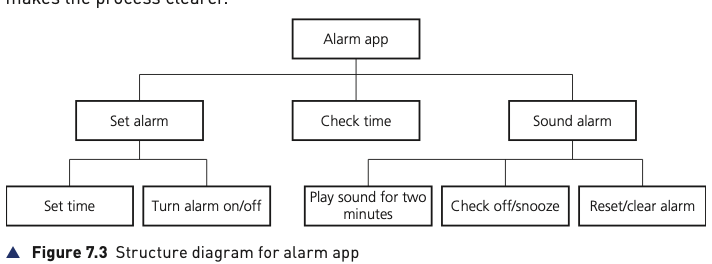
A structure diagram shows top-down design in hierarchical form. Each lower level gives a more detailed breakdown of the system.
Flowcharts
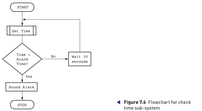
A flowchart shows the steps needed to complete a task and the order in which they are carried out. These ordered steps form an algorithm.
Standard flowchart symbols
Cambridge flowcharts use standard symbols for start/end, processes, input/output, decisions and flow lines.
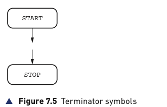
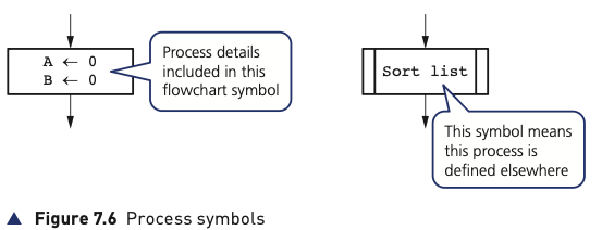
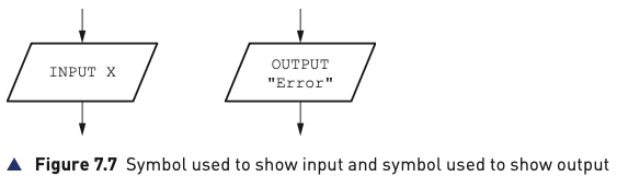
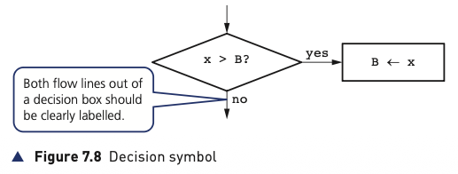
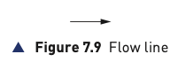
Decision symbols always have two labelled outputs. Flow lines use arrows to show the direction of control, usually top-to-bottom and left-to-right.
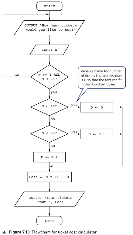
Pseudocode
Pseudocode describes an algorithm using English-like keywords similar to a high-level language, but without the strict syntax rules of a real programming language. In the textbook, keywords such as INPUT, OUTPUT, IF and WHILE are capitalised, data item and subroutine names start with a capital letter, and nested/repeated statements are indented.
Assignment and mathematical operators
The assignment operator ← gives a variable the value of the expression on the right. Mathematical operators include +, −, *, /, ^ and parentheses.
Cost ← 10
Price ← Cost * 2
Tax ← Price * 0.12
SellingPrice ← Price + Tax
Conditional statements
IF … THEN … ELSE … ENDIF selects between true and false paths. CASE OF … OTHERWISE … ENDCASE selects one of several possible values. Conditions can use Boolean values and comparison/logical operators such as >, <, =, >=, <=, <>, AND, OR, NOT.
IF Age < 18
 THEN
  OUTPUT "Child"
 ELSE
  OUTPUT "Adult"
ENDIF
An IF statement placed inside another IF is a nested IF.
Iteration
| Loop | When used |
|---|---|
FOR … TO … NEXT | When the number of repetitions is known. |
REPEAT … UNTIL | When the number of repetitions is not known and the loop must run at least once. The condition is tested at the end (post-condition). |
WHILE … DO … ENDWHILE | When the number of repetitions is not known and the loop may run zero times. The condition is tested at the start (pre-condition). |
Input and output
INPUT is used to enter data into a variable. OUTPUT displays information. The source notes that READ is commonly associated with files and PRINT may be used when hard copy is required.
INPUT Name
INPUT StudentMark
OUTPUT Name
OUTPUT "Your name is ", Name