10.3 Logic circuits, logic expressions, truth tables and problem statements
This final topic brings the whole Boolean-logic chapter together. You need to move confidently between logic circuits, logic or Boolean expressions, truth tables and real problem statements.
What Topic 10.3 expects you to do
The textbook organises this topic around eight worked examples. Across them, you must be able to perform three-way conversions:
| Starting information | You may be asked to produce |
|---|---|
| Problem statement | Logic circuit, truth table, logic/Boolean expression |
| Logic/Boolean expression | Logic circuit and truth table |
| Truth table | Logic/Boolean expression and logic circuit |
| Logic circuit | Truth table and logic/Boolean expression |
A AND B is equally useful for following the worked methods.Logic circuit → truth table
Example 1: trace a circuit in stages
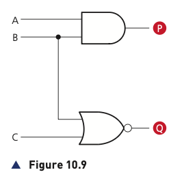
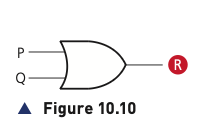
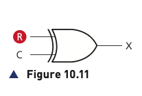
When a circuit contains several gates, do not try to calculate the final output in one jump. The book splits the circuit into stages and gives intermediate outputs names such as P, Q and R. With three inputs there are 2³ = 8 possible input combinations, so the final truth table needs eight rows.
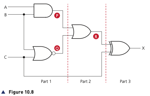
For the circuit in Figure 10.8:
- P is produced by an AND gate using A and B.
- Q is produced by a NOR gate using B and C.
- R is produced by combining P and Q with an OR gate.
- X is then obtained by combining R and C with an XOR gate.
| A | B | C | P | Q | R | X |
|---|---|---|---|---|---|---|
| 0 | 0 | 0 | 0 | 1 | 1 | 1 |
| 0 | 0 | 1 | 0 | 0 | 0 | 1 |
| 0 | 1 | 0 | 0 | 0 | 0 | 0 |
| 0 | 1 | 1 | 0 | 0 | 0 | 1 |
| 1 | 0 | 0 | 0 | 1 | 1 | 1 |
| 1 | 0 | 1 | 0 | 0 | 0 | 1 |
| 1 | 1 | 0 | 1 | 0 | 1 | 1 |
| 1 | 1 | 1 | 1 | 0 | 1 | 0 |
Logic circuit → logic expression
Example 2: work from the input side towards the output
Start with the gates directly connected to the inputs. Write an expression for each of these first. Then replace each intermediate gate with its expression as you move towards the output.
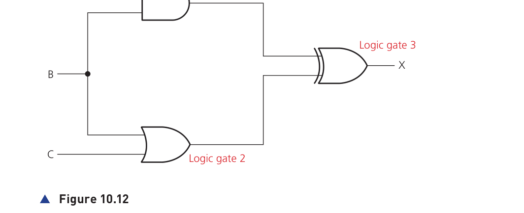
Figure 10.12
Gate 1 gives (A AND B). Gate 2 gives (B OR C). Gate 3 joins those results using XOR.
Final expression: (A AND B) XOR (B OR C).
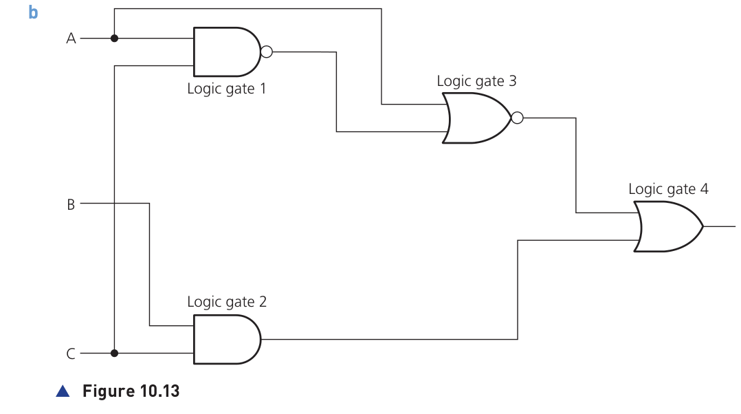
Figure 10.13
The source works through the gates in order: (A NAND C) and (B AND C) first, then applies NOR with A, before the final OR.
Final expression: ((A NAND C) NOR A) OR (B AND C).
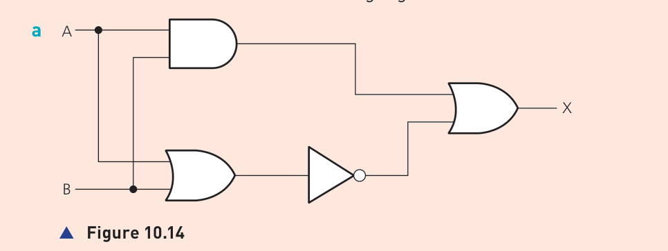
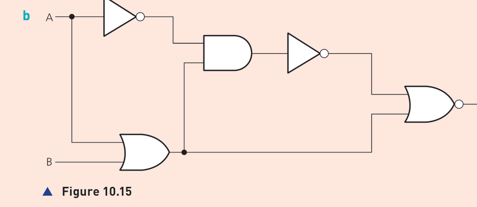
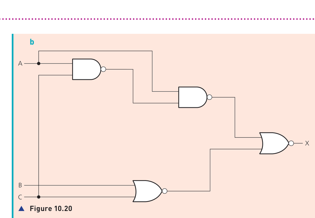
Activity 10.2: practise with the original circuits
The textbook then gives a set of circuits for students to convert into truth tables and expressions. The original figures are kept here so you practise with the same visual gate symbols and wiring style.
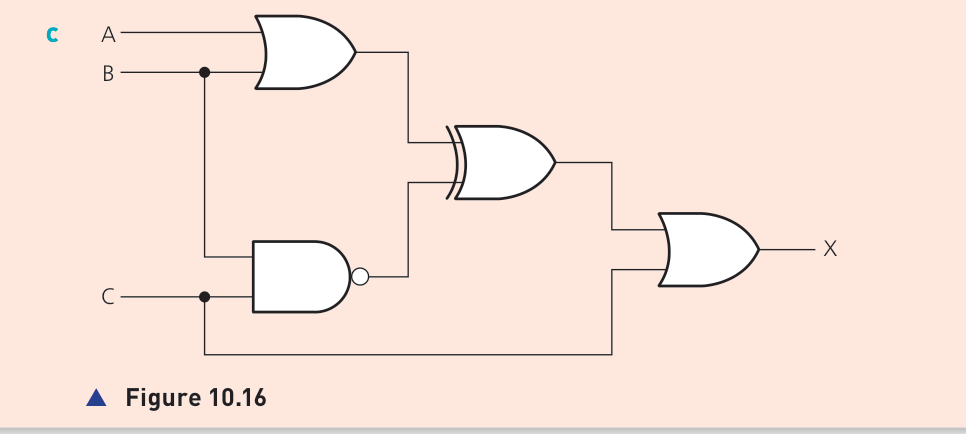
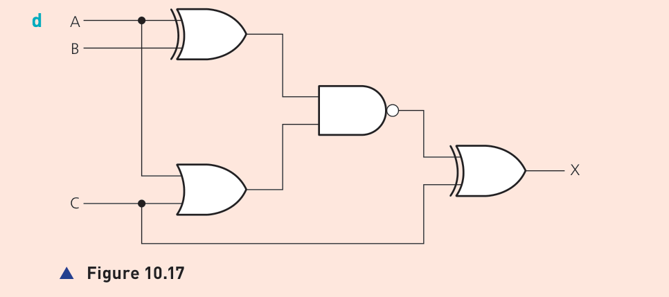
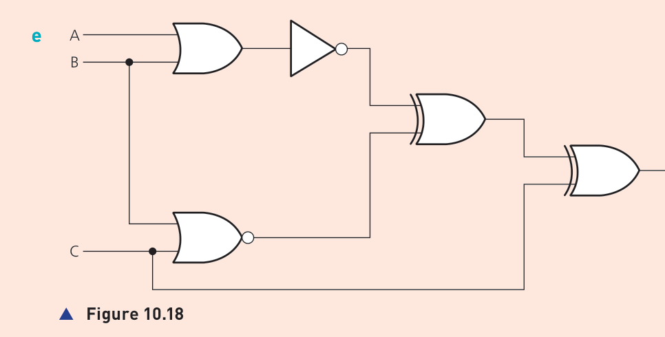
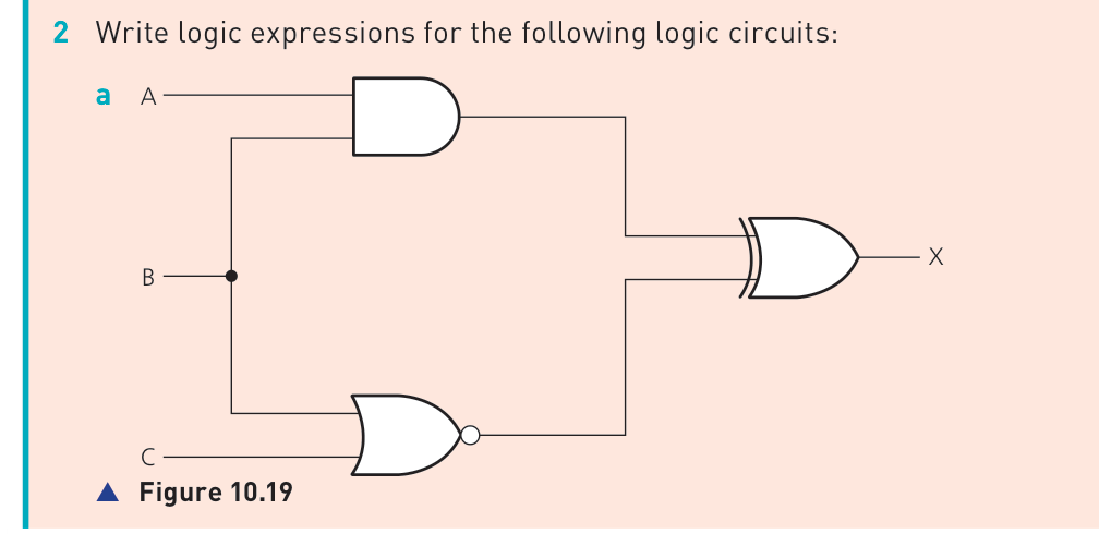
Logic expression → circuit and truth table
Example 3: build the expression one bracket at a time
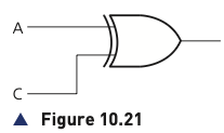
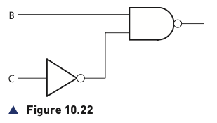
The source expression is (A XOR C) OR (NOT C NAND B). The outermost operation is OR, so the two bracketed parts can be built separately and then joined with an OR gate.
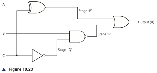
| A | B | C | P | Q | R | X |
|---|---|---|---|---|---|---|
| 0 | 0 | 0 | 0 | 1 | 1 | 1 |
| 0 | 0 | 1 | 1 | 0 | 1 | 1 |
| 0 | 1 | 0 | 0 | 1 | 0 | 0 |
| 0 | 1 | 1 | 1 | 0 | 1 | 1 |
| 1 | 0 | 0 | 1 | 1 | 1 | 1 |
| 1 | 0 | 1 | 0 | 0 | 1 | 1 |
| 1 | 1 | 0 | 1 | 1 | 0 | 1 |
| 1 | 1 | 1 | 0 | 0 | 1 | 1 |
Truth table → expression and circuit
Example 4: use the rows where X = 1
The book's method is to look only at rows where the output is 1. For each such row, write an AND expression that exactly describes the input pattern. An input of 0 is written as NOT that input. If more than one row produces 1, join the row expressions using OR.
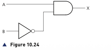
For the first table, only A = 1 and B = 0 produces X = 1, giving A AND NOT B.
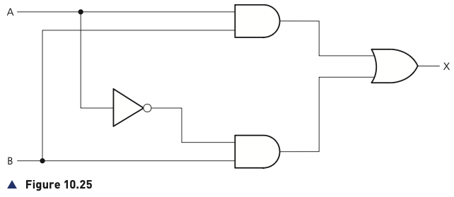
For the second table, two rows produce X = 1, giving (NOT A AND B) OR (A AND B).
Example 5: three-input truth tables
With three inputs, each output-1 row becomes a three-part AND expression. For example, the first truth table in the source produces:
Expression from the output-1 rows
(NOT A AND NOT B AND NOT C) OR (A AND NOT B AND NOT C) OR (A AND B AND NOT C)The second example uses four output-1 rows. The source then proves by truth table that the longer expression gives the same outputs as the shorter expression (B AND C) OR (A AND C) OR (A AND B).
Problem statement → expression, circuit and truth table
Example 6: convert ON/OFF wording into logic
The safety-system statement says the alarm X sounds if A is ON and B is OFF, or if B is ON and C is OFF. Since ON = 1 and OFF = 0, OFF is represented by NOT.
(A AND NOT B) OR (B AND NOT C).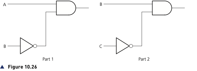
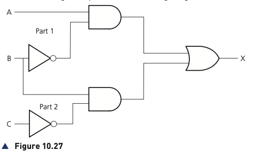
| A | B | C | A AND NOT B | B AND NOT C | X |
|---|---|---|---|---|---|
| 0 | 0 | 0 | 0 | 0 | 0 |
| 0 | 0 | 1 | 0 | 0 | 0 |
| 0 | 1 | 0 | 0 | 1 | 1 |
| 0 | 1 | 1 | 0 | 0 | 0 |
| 1 | 0 | 0 | 1 | 0 | 1 |
| 1 | 0 | 1 | 1 | 0 | 1 |
| 1 | 1 | 0 | 0 | 1 | 1 |
| 1 | 1 | 1 | 0 | 0 | 0 |
Example 7: wind-turbine safety system
First translate the physical conditions into the binary meanings given in the table. The three shutdown conditions become:
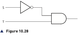
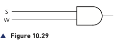
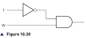
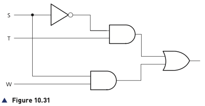
NOT S AND T— turbine speed is at or below 1000 rpm and bearing temperature is above 80°C.S AND W— turbine speed is above 1000 rpm and wind velocity is above 120 kph.NOT T AND W— bearing temperature is at or below 80°C and wind velocity is above 120 kph.
Because the original conditions are joined by OR, the three sub-circuits are ORed together.
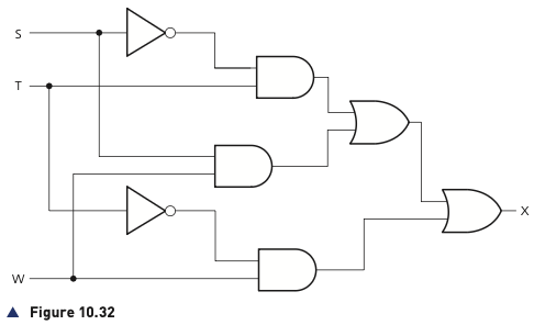
| S | T | W | NOT S AND T | S AND W | NOT T AND W | X |
|---|---|---|---|---|---|---|
| 0 | 0 | 0 | 0 | 0 | 0 | 0 |
| 0 | 0 | 1 | 0 | 0 | 1 | 1 |
| 0 | 1 | 0 | 1 | 0 | 0 | 1 |
| 0 | 1 | 1 | 1 | 0 | 0 | 1 |
| 1 | 0 | 0 | 0 | 0 | 0 | 0 |
| 1 | 0 | 1 | 0 | 1 | 1 | 1 |
| 1 | 1 | 0 | 0 | 0 | 0 | 0 |
| 1 | 1 | 1 | 0 | 1 | 0 | 1 |
Further textbook practice in Topic 10.3
The source then provides additional problems involving chemical-process alarms, power-station shutdown systems, car engine-management warnings and further expressions/truth tables. The important method is always the same:
- Translate each physical condition into a binary meaning.
- Look for AND, OR and conditions that require NOT.
- Write the expression in manageable parts.
- Draw the circuit from those parts.
- Complete all possible input rows in the truth table.
- Use the truth table to check that the expression and circuit agree.