10.2 The function of the six logic gates
Each standard logic gate follows a precise rule for turning binary input values into a binary output. This topic covers the function, truth table and notation for all six gates: NOT, AND, OR, NAND, NOR and XOR.
10.2.1 NOT gate
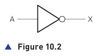
A NOT gate has one input. It reverses, or inverts, the input value.
| Input A | Output X |
|---|---|
| 0 | 1 |
| 1 | 0 |
X = NOT ABoolean algebra:
X = The NOT gate is the only one of the six standard gates in this topic with a single input. Its output is always the opposite binary value from its input.
10.2.2 AND gate
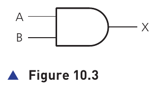
An AND gate has two inputs. Its output is 1 only when both inputs are 1.
| Input A | Input B | Output X |
|---|---|---|
| 0 | 0 | 0 |
| 0 | 1 | 0 |
| 1 | 0 | 0 |
| 1 | 1 | 1 |
X = A AND BBoolean algebra:
X = A · BA quick way to remember the rule is that an AND gate requires all its inputs to be 1 before the output can become 1.
10.2.3 OR gate
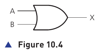
An OR gate has two inputs. Its output is 1 when either input is 1, or both inputs are 1.
| Input A | Input B | Output X |
|---|---|---|
| 0 | 0 | 0 |
| 0 | 1 | 1 |
| 1 | 0 | 1 |
| 1 | 1 | 1 |
X = A OR BBoolean algebra:
X = A + BOnly the input combination 0, 0 produces an output of 0. Every other two-input combination produces 1.
10.2.4 NAND gate (NOT AND)
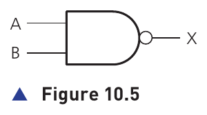
A NAND gate is the opposite of an AND gate. The name comes from NOT AND.
| Input A | Input B | Output X |
|---|---|---|
| 0 | 0 | 1 |
| 0 | 1 | 1 |
| 1 | 0 | 1 |
| 1 | 1 | 0 |
X = A NAND BBoolean algebra:
X = Compare this table with the AND table: every output has been inverted.
10.2.5 NOR gate (NOT OR)
A NOR gate is the opposite of an OR gate. The name comes from NOT OR.
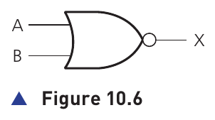
| Input A | Input B | Output X |
|---|---|---|
| 0 | 0 | 1 |
| 0 | 1 | 0 |
| 1 | 0 | 0 |
| 1 | 1 | 0 |
X = A NOR BBoolean algebra:
X = Compare this with OR: each OR output is reversed. NOR gives 1 only for 0, 0.
10.2.6 XOR gate
An XOR gate has two inputs. Its output is 1 when the two input values are different.
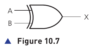
| Input A | Input B | Output X |
|---|---|---|
| 0 | 0 | 0 |
| 0 | 1 | 1 |
| 1 | 0 | 1 |
| 1 | 1 | 0 |
X = A XOR BBoolean algebra:
X = (A · ) + ( · B)Alternative shown in the source:
X = (A + B) · This gate differs from OR at the 1, 1 row. OR outputs 1 when both inputs are 1; XOR outputs 0 because XOR requires the two inputs to be different.
Activity 10.1 idea: two expressions for XOR
The source asks you to show that these two logic statements represent the same gate:
(A AND NOT B) OR (NOT A AND B)(A OR B) AND (NOT (A AND B))
Both produce 1 for 0,1 and 1,0, and 0 for 0,0 and 1,1. They therefore have the same truth table as XOR.
| A | B | First expression | Second expression |
|---|---|---|---|
| 0 | 0 | 0 | 0 |
| 0 | 1 | 1 | 1 |
| 1 | 0 | 1 | 1 |
| 1 | 1 | 0 | 0 |
Logic notation and Boolean algebra symbols
The textbook also introduces three Boolean-algebra symbols used alongside the logic notation:
| Boolean symbol | Meaning | Example |
|---|---|---|
| · | AND | A · B |
| + | OR | A + B |
| NOT | |