2.1 Types and methods of data transmission
When data moves between devices, it has to be organised, routed and transmitted in a form the receiving device can reconstruct correctly. This topic explains data packets and packet switching, the main transmission modes and methods, and how USB provides a standard serial connection between devices.
What you need to understand
By the end of Topic 2.1 you should be able to describe the structure of a data packet and the role of routers in packet switching; distinguish simplex, half-duplex and full-duplex transmission; compare serial and parallel transmission; and explain how USB connects devices, including the role of automatic detection and device drivers.
Data packets
Data sent over long distances is normally divided into smaller units called data packets or datagrams. The textbook describes these packets as typically being around 64 KiB. Sending smaller packets is easier to control than trying to send one long continuous stream of data, and it allows different packets to take different routes through a network.
Packet structure
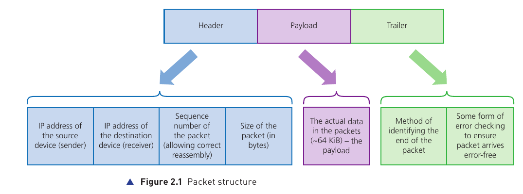
A typical packet has three main parts: a header, a payload and a trailer.
Header
Contains control information needed to deliver and reassemble the packet, including the source IP address, destination IP address, packet sequence number and packet size. A header may also include the total number of packets in the transmission.
Payload
The actual data being carried by the packet. In the textbook example, the payload is usually about 64 KiB.
Trailer
Contains information that marks the end of the packet and an error-checking value so the receiver can detect whether the packet was corrupted in transmission.
What the header does
- Source IP address: identifies the sending device.
- Destination IP address: identifies the receiving device and helps routers decide where the packet should go.
- Sequence number: lets the receiving system put packets back into the original order.
- Packet size: helps the receiver check that the packet has arrived intact.
Error checking in the trailer
The textbook introduces a cyclic redundancy check (CRC) here as the error-checking value carried in the trailer. In the simplified explanation used in this topic, the sender calculates a value from the payload and stores it in the trailer. The receiver recalculates the value after the packet arrives and compares the two results. If they do not match, the packet is treated as damaged and must be sent again.
Packet switching
Packet switching is a method in which a message is split into packets and the packets are sent independently across the network. Each stage of the route contains a router. A router reads information in the packet header — especially the destination address — and decides where to send the packet next.
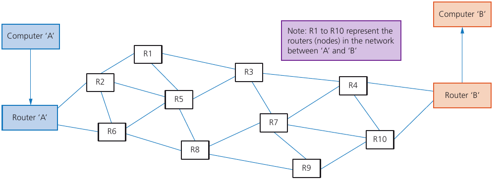
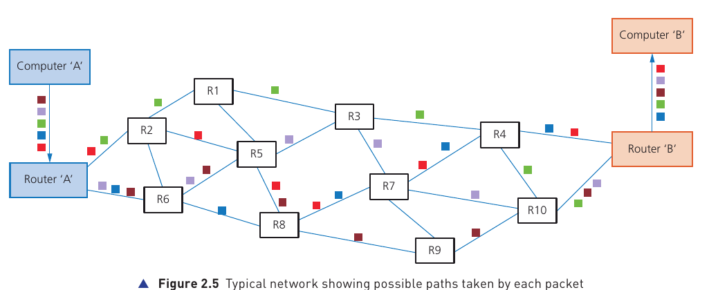
Packets do not have to follow the same route. The route selected at each stage depends on what paths are available and how busy different nodes are. The shortest available route is selected, which may not be the shortest theoretical route if parts of the network are busy or unsuitable.
What happens at the destination?
- The receiving device collects the packets that arrive.
- Sequence numbers in the headers are used to restore the correct order.
- If a packet is missing or damaged, the system can request that the relevant packet is sent again.
- Once the required packets are present and correctly ordered, the original data can be reconstructed.
Benefits and drawbacks of packet switching
| Benefits | Drawbacks |
|---|---|
| No need to reserve one communication line for the whole transmission. | Packets can be lost and may need to be re-sent. |
| Failed, busy or faulty routes can be avoided by re-routing packets. | Real-time streaming can be affected by delays, missing packets or packets arriving at different times. |
| Network usage can be expanded relatively easily. | The receiver may need time to put packets back into the correct order. |
| A high data-transmission rate can be possible. | More control information is needed because each packet requires a header and trailer. |
Data transmission
Data may travel only a short distance, such as from one device to another nearby, or across a global network. The textbook highlights three factors to consider:
- Direction: can data travel in one direction only, or in both directions?
- Method: how many bits are sent at the same time?
- Synchronisation: how does the system make sure the received data is in the correct order?
These rules are normally governed by a communication protocol.
Simplex, half-duplex and full-duplex
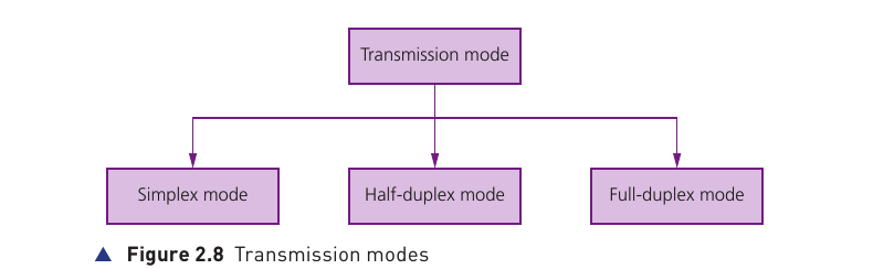
Simplex
Data travels in one direction only. The textbook example is data sent from a computer to a printer.
Half-duplex
Data can travel in both directions, but not at the same time. A walkie-talkie is the textbook example: one person transmits while the other receives.
Full-duplex
Data can travel in both directions at the same time. A broadband internet connection is given as an example.
Serial data transmission
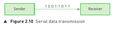
Serial transmission sends one bit at a time along a single wire or channel. The bits travel one after another as a stream.
- Works well over long distances.
- Uses fewer wires, so hardware requirements and cost can be lower.
- Has less risk of external interference than a multi-wire parallel connection.
- The bits do not suffer from skew between multiple channels because there is only one data channel.
- It is generally slower than parallel transmission when comparing the simple textbook models.
- USB uses serial data transmission.
Parallel data transmission
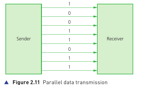
Parallel transmission sends several bits at the same time using several wires or channels. A common classroom example is sending one byte (eight bits) simultaneously along eight separate channels.
- Can provide a faster data rate over short distances.
- Requires more wires and therefore more hardware.
- Over longer distances, different bits can arrive at slightly different times. This is called skew.
- Skew can make the received bits unsynchronised or out of order.
- Parallel transmission is used inside computers, where distances between components are short and high-speed transmission is important.
Serial versus parallel
| Feature | Serial | Parallel |
|---|---|---|
| Bits sent at once | One bit | Several bits |
| Channels/wires | One data channel | Several data channels |
| Best distance | Longer distances | Shorter distances |
| Skew risk | Low because bits share one channel | Higher over longer distances because separate bits may arrive at different times |
| Hardware | Fewer wires; usually cheaper | More wires; usually more expensive |
| Typical use in this topic | USB and longer-distance links | Internal computer pathways where distances are short |
Universal serial bus (USB)
USB stands for Universal Serial Bus. It is a standard form of serial communication used to connect peripherals and other devices to a computer. In the textbook's description, USB can support both half-duplex and full-duplex data transmission.
USB cable structure
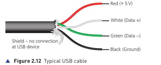
The standard cable shown in the book has four shielded wires:
Red
Power: +5 V.
Black
Ground.
White
One of the two data signal wires.
Green
The other data signal wire.
What happens when a USB device is connected?
- The computer detects that a device is present.
- The device is identified.
- The appropriate device driver is loaded so the computer and device can communicate.
- If the required driver is not already available, the system may prompt the user to install or download it.
USB-C in the supplied textbook
The textbook describes USB-C as a 24-pin symmetrical connector that can be inserted either way round. It also describes support for power delivery and high data rates, and notes backward compatibility with older USB standards when a suitable adaptor is used.
Benefits and drawbacks of USB
| Benefits | Drawbacks |
|---|---|
| Devices can be automatically detected and drivers can be loaded automatically. | Standard USB cable length is limited; the book notes that hubs may be required for longer runs. |
| USB has become an industry-standard connection with wide support. | Very old USB standards may not always be supported on newer computers. |
| One cable can carry data and also supply power to many connected devices. | USB data rates can be slower than some dedicated networking technologies. |
| The protocol can request re-transmission if an error is detected. | Different USB versions, connectors and adaptors can create compatibility or performance differences. |
| Extra ports can be added using USB hubs. | A hub shares the connection and does not remove all physical distance or bandwidth limitations. |
| Backward compatibility allows many older USB devices to continue working. | Backward compatibility may require a suitable adaptor or may operate at an older device's lower capability. |