10.1 Standard logic gate symbols
Logic gates are the building blocks of digital electronic circuits. In this topic you need to recognise the six standard gate symbols and understand how truth tables organise every possible combination of binary inputs.
10.1.1 Logic gate symbols
Electronic circuits in computers, solid-state drives and control devices are made from large numbers of logic gates. A logic gate accepts one or more binary inputs and produces a binary output. Binary means that each input or output can have only one of two states: 0 or 1.
Several gates can be connected together to form a logic circuit. A logic circuit is designed to perform a particular function. The output produced by a gate or a whole circuit can be checked systematically using a truth table.
The six standard gates
The six gates introduced in the textbook are:
- NOT
- AND
- OR
- NAND
- NOR
- XOR
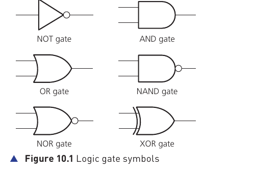
| Gate | Number of inputs in this course | Output |
|---|---|---|
| NOT | 1 | 1 binary output |
| AND | 2 | 1 binary output |
| OR | 2 | 1 binary output |
| NAND | 2 | 1 binary output |
| NOR | 2 | 1 binary output |
| XOR | 2 | 1 binary output |
Truth tables
A truth table is used to trace the output of a logic gate or a logic circuit. It lists every possible combination of binary inputs and then shows the output produced for each combination.
The NOT gate has only one input. The other five standard gates shown in Figure 10.1 have two inputs. A complete truth table must include every possible input combination, so the number of rows grows as the number of inputs increases.
All possible input combinations
| 2 inputs · 2² = 4 | |
|---|---|
| A | B |
| 0 | 0 |
| 0 | 1 |
| 1 | 0 |
| 1 | 1 |
| 3 inputs · 2³ = 8 | ||
|---|---|---|
| A | B | C |
| 0 | 0 | 0 |
| 0 | 0 | 1 |
| 0 | 1 | 0 |
| 0 | 1 | 1 |
| 1 | 0 | 0 |
| 1 | 0 | 1 |
| 1 | 1 | 0 |
| 1 | 1 | 1 |
| 4 inputs · 2⁴ = 16 | |||
|---|---|---|---|
| A | B | C | D |
| 0 | 0 | 0 | 0 |
| 0 | 0 | 0 | 1 |
| 0 | 0 | 1 | 0 |
| 0 | 0 | 1 | 1 |
| 0 | 1 | 0 | 0 |
| 0 | 1 | 0 | 1 |
| 0 | 1 | 1 | 0 |
| 0 | 1 | 1 | 1 |
| 1 | 0 | 0 | 0 |
| 1 | 0 | 0 | 1 |
| 1 | 0 | 1 | 0 |
| 1 | 0 | 1 | 1 |
| 1 | 1 | 0 | 0 |
| 1 | 1 | 0 | 1 |
| 1 | 1 | 1 | 0 |
| 1 | 1 | 1 | 1 |
The order above follows binary counting. For example, a three-input truth table begins at 000 and ends at 111. A four-input table begins at 0000 and ends at 1111. When outputs are added later, each input row gets the corresponding output value for the gate or circuit being tested.