3.1 Computer architecture
This topic explains how the CPU, memory, registers and buses work together; how instructions move through the Fetch–Decode–Execute cycle; what affects CPU performance; what an instruction set contains; and how embedded systems use specialised hardware and software to perform dedicated tasks.
What you need to understand
By the end of Topic 3.1 you should be able to describe the main parts of a CPU and von Neumann architecture; state the roles of the main special-purpose registers and system buses; trace the Fetch–Decode–Execute cycle; explain how clock speed, cache, cores and bus width affect performance; distinguish opcode from operand; and explain how embedded systems work, including their benefits, drawbacks and applications.
The central processing unit (CPU)
The central processing unit (CPU), also called a processor or microprocessor, is responsible for executing and processing the instructions and data used by computer applications. It is commonly implemented as an integrated circuit on a single microchip.
Control Unit (CU)
Coordinates the computer. It reads and interprets instructions and sends control signals to other components so that operations happen in the correct order.
Arithmetic & Logic Unit (ALU)
Performs arithmetic operations such as addition, subtraction and logical shifts, and logic operations such as AND and OR.
Registers
Very small, very fast storage locations within the CPU used to hold instructions, addresses and data temporarily while processing is taking place.
System clock
Produces timing signals that synchronise operations throughout the processor and computer system.
Von Neumann architecture
John von Neumann's stored-program concept introduced a model in which program instructions and data are stored in memory and the CPU can access that memory directly. Instructions can then be fetched and executed in sequence. This became the basis of modern stored-program computers.
- A central processing unit is used.
- The CPU can directly access memory.
- The same memory can store both programs and data.
- Stored programs consist of instructions that can be executed sequentially.
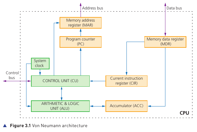
CPU components in the architecture
The ALU carries out arithmetic and logical operations. The CU manages the instruction-processing sequence and sends control signals. The system clock provides the timing needed to keep all components synchronised.
RAM temporarily stores programs and data that the CPU needs. The textbook also describes RAM as the Immediate Access Store (IAS). Using RAM is much faster than repeatedly reading from backing storage.
Special-purpose registers
| Register | Abbreviation | Purpose |
|---|---|---|
| Current Instruction Register | CIR | Stores the current instruction while it is being decoded and executed. |
| Accumulator | ACC | Stores data temporarily while the ALU is carrying out calculations. |
| Memory Address Register | MAR | Stores the address of the memory location currently being read from or written to. |
| Memory Data Register | MDR | Stores data just read from memory or data about to be written to memory. |
| Program Counter | PC | Stores the address of the next instruction to be fetched. |
System buses
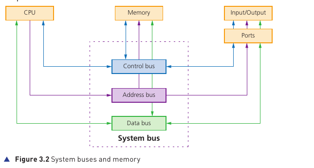
| Bus | Direction | What it carries | Why width matters |
|---|---|---|---|
| Address bus | Between CPU and memory it is unidirectional. | Memory addresses. | A wider address bus lets the CPU address more memory locations. A 16-bit address bus can address 216 locations. |
| Data bus | Bidirectional. | Data between CPU, memory and input/output devices. In this context, the transmitted data may be an instruction, numerical value or other stored content. | A wider data bus carries a larger word at one time and can improve performance. |
| Control bus | Bidirectional. | Control and timing signals between the CU and other components. | The source notes that it does not need to be as wide as the data or address buses because it carries control signals. |
Memory read and write operations
Reading from memory
- The address of the required memory location is placed in the MAR.
- A read signal is sent to memory.
- The contents of that memory location are placed in the MDR.
Writing to memory
- The value to be stored is placed in the MDR.
- The destination address is placed in the MAR.
- A write signal is sent and the value in the MDR is written to that memory location.
Fetch–Decode–Execute cycle
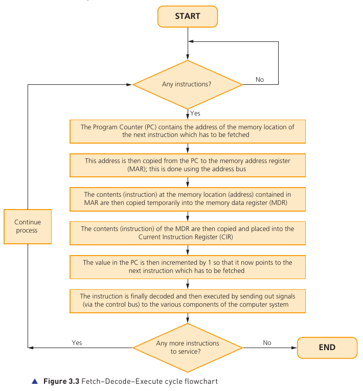
- The PC holds the address of the next instruction.
- That address is copied from the PC to the MAR using the address bus.
- The instruction stored at that memory address is copied to the MDR.
- The instruction in the MDR is copied to the CIR.
- The PC is incremented so that it points to the next instruction.
- The instruction in the CIR is decoded.
- It is then executed; control signals are sent to the appropriate components using the control bus.
- The cycle repeats for subsequent instructions.
Cores, cache and internal clock
CPU performance is affected by several interacting factors. A faster value in one area does not automatically mean overall performance will increase by exactly the same amount.
Clock speed
The system clock generates clock cycles that synchronise computer operations. A clock speed of 3.5 GHz means approximately 3.5 billion clock cycles per second. Increasing clock speed can potentially increase processing speed because more cycles can occur each second.
Cache memory
Cache is fast memory located within or very close to the CPU. It stores frequently used data and instructions so that the CPU can access them faster than if it had to retrieve them from main memory every time. The CPU checks cache first and moves to RAM if the required item is not present.
A larger or more effective cache can improve processor performance because more frequently used information can be kept close to the CPU.
Processor cores
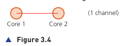
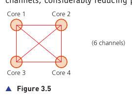
A core contains the processor components needed to execute instructions, including an ALU, control unit and registers. A dual-core CPU has two cores; a quad-core CPU has four.
More cores can allow more processing to take place without continually increasing clock speed, but doubling the number of cores does not necessarily double performance. The cores and CPU still need to communicate and software must be able to make effective use of multiple cores.
Bus width
Performance can also be affected by the width of the address bus and data bus. A wider address bus permits more memory locations to be addressed, while a wider data bus can transfer a larger word in one operation.
Instruction set
An instruction set is the limited collection of low-level operations that a particular CPU can understand and execute. Programs ultimately need to be translated into instructions from the processor's instruction set.
Opcode
The part of an instruction that tells the CPU which operation to perform, for example an operation such as ADD, JMP or LDA.
Operand
The part that identifies the data, memory location or register that the operation acts on.
The Fetch–Decode–Execute cycle processes these instructions in sequence. The CU decodes the operation and coordinates the necessary action; the ALU carries out calculations or logical operations when required.
Embedded systems
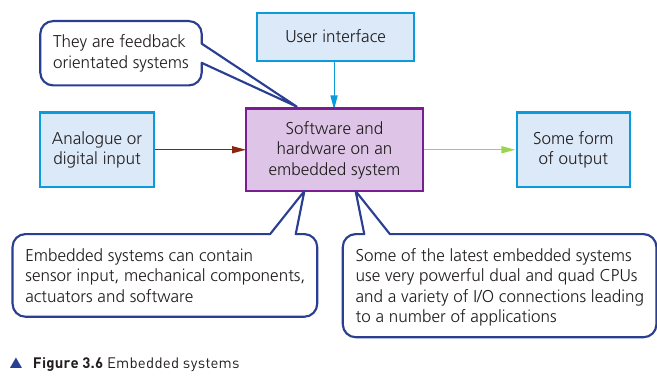
An embedded system combines hardware and software to carry out a specific set of functions. Unlike a general-purpose computer, it is designed around a particular task or small group of closely related tasks.
| Type | What the textbook describes |
|---|---|
| Microcontroller | A CPU together with some RAM, ROM and other peripherals on one chip. Together they carry out a specific task. |
| Microprocessor | An integrated circuit containing the CPU, with RAM, ROM and peripherals added separately. |
| System on Chip (SoC) | A highly integrated chip that may contain a microcontroller and commonly includes CPU, memory, input/output ports and secondary storage. |
Inputs, processing, outputs and feedback
Inputs may come from a user interface, such as a keypad or dial, or automatically from sensors. Inputs may be analogue or digital. The embedded system processes the input and produces an output, often by sending a signal to a component such as an actuator. Many embedded systems operate as feedback-oriented systems, responding continually to changing input.
Programmable embedded devices can receive software updates by connecting to a computer or automatically through wireless links such as Wi-Fi, satellite or cellular networks. Non-programmable systems generally cannot be updated in the same way.
Benefits and drawbacks
| Benefits | Drawbacks |
|---|---|
| Small and easy to fit inside a device. | Some devices are difficult to upgrade when technology changes. |
| Relatively low manufacturing cost. | Troubleshooting can require specialist knowledge. |
| Dedicated to one task, allowing a simple interface and sometimes no full operating system. | A seemingly simple interface can still be confusing to operate. |
| Low power consumption. | Internet-connected embedded systems can be exposed to hackers, malware or other network threats. |
| Can often be controlled remotely. | Difficult repair or upgrading can encourage devices to be discarded rather than repaired. |
| Can react very quickly to changing input and operate in real time. | Frequent replacement can contribute to a throw-away culture and electronic waste. |
| Mass production can improve reliability. | — |
Examples of embedded systems
Motor vehicles
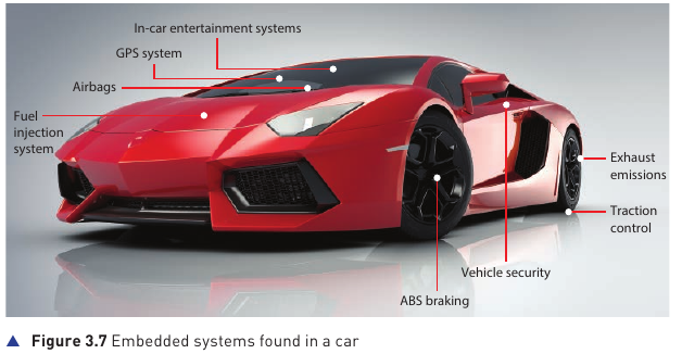
Modern vehicles contain many embedded systems controlling or assisting systems such as fuel injection, airbags, ABS braking, traction control, vehicle security, exhaust emissions, GPS and in-car entertainment.
Set-top box
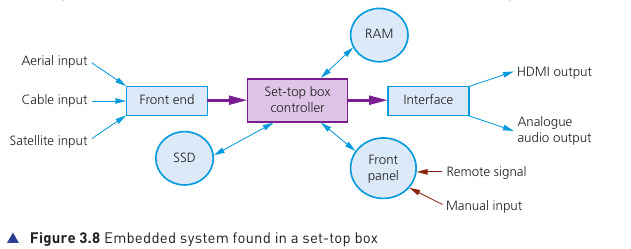
A set-top box can use an embedded controller to coordinate recording and playback, storage on an SSD, incoming aerial/cable/satellite signals, a front panel or remote input, RAM and outputs such as HDMI and analogue audio.
Security system
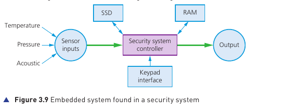
Security systems can accept input from temperature, pressure or acoustic sensors and a keypad. The controller compares input with stored settings and may produce outputs such as lights, alarms or messages to the owner.
Lighting systems
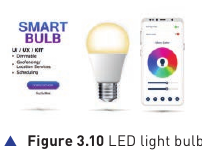
Embedded lighting controllers can take account of the time or day, room occupancy and natural light level. They can reduce energy use, restore lighting when movement is detected, dim lights when daylight is strong and provide emergency lighting when required. Some systems can control individual Bluetooth/LED bulbs.
Vending machines
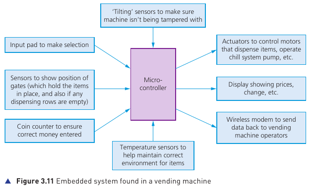
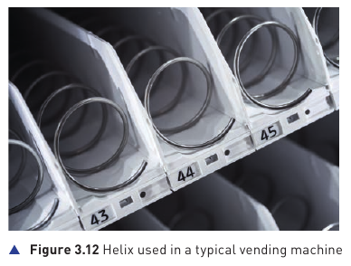
A vending-machine microcontroller can receive input from a selection keypad, coin counter, temperature sensors, gate-position sensors and a tilt sensor. It can operate motors and cooling equipment through actuators, update a display and send sales or stock information back to the operator.
Washing machines and other white goods
Appliances such as washing machines, refrigerators and microwave ovens use embedded systems to take selections such as temperature, wash cycle or cooking time and then control the required sequence automatically. Internet-enabled versions may also support remote operation.